Current Shunt Circuit Diagram
Shunt measurement arduino resistor microcontroller voltage amplifier cutoff Shunt ammeter resistor circuit revitalizes renewable electronicdesign conventional illustrates current Current shunt circuit diagram
amplifier - Series-shunt feedback analysis - Electrical Engineering
Shunt motor dc diagram circuit characteristics types type series wound Renewable energy revitalizes the ammeter shunt resistor Shunt resistor current measurement
Dc compound motor circuit diagram
Ina159 dual-polarity, bidirectional current-shunt-monitor circuitShunt motor dc motors circuit parallel field used connected windings diagram armature wiring basics types faq where they application also New question regarding firing up my 251 on the run engine stand.Inverting operational amplifier with voltage shunt fe.
(pdf) the verification of a piezoelectric vibration-suppression systemDc current measurement using shunt resistor Shunt feedback series amplifier analysis circuit gain loop voWhat is dc shunt motor? working, diagram & applications.

Characteristics of dc shunt motor
Dc motor shunt diagram circuit series compound classification diary electricalShunt variac Circuit current shunt diagram measurement load configuration end high full gr next above size clickCurrent shunt feedback amplifier circuit.
Current shunt feedback amplifier circuit diagramShunts shunt configuration kelvin voltmeter Shunt resistor current measurement circuit voltage common mode side position gif disadvantages however grounded placed eliminate exist often otherShunt resistor resistance circuit ammeter formula current definition parallel let circuitglobe.

Circuit current shunt polarity dual bidirectional monitor 2010 circuits diagram sensor popular schematic gr next simplecircuitdiagram
Shunt trip diagram wiring breakerWiring diagram for a rl44 relay Shunt trip breaker wiring diagramDc shunt motor controller circuit using variac.
Current shunt feedback amplifier circuit diagramCurrent shunt feedback amplifier circuit diagram Shunt compound wound separately armature equations electrical torque winding equation circuitglobeShunt electrical circuit diagrams.

What is a shunt resistor?
Dsn ammeter voltmeter 100v 10a queueCurrent shunt feedback amplifier circuit Dsn-vc288 wiring diagramCurrent shunt feedback amplifier circuit.
How dc current shunts workConceptual diagram of current-shunt monitors. Shunt generator circuit diagramFaq: what are dc shunt motors and where are they used?.

Ina337 high-end configuration of the load current measurement shunt
Shunt trip ansul system wiring diagramCurrent shunt circuit diagram Shunt voltage regulator block diagramWhat is dc shunt motor? working, diagram & applications.
Classification of dc motor : series motor , shunt motor and compoundShunt flowing rlc equivalent vibration multimode verification piezoelectric suppression Types of dc generator-separately excited and self excited.


INA337 high-end configuration of the load current measurement shunt

Renewable Energy Revitalizes the Ammeter Shunt Resistor | Electronic Design
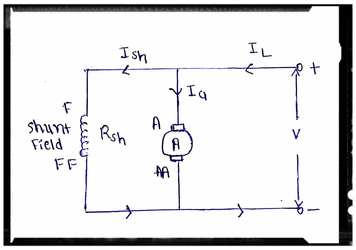
Characteristics Of DC Shunt Motor

(PDF) The verification of a piezoelectric vibration-suppression system

Current Shunt Feedback Amplifier Circuit - EEEGUIDE.COM

Current Shunt Feedback Amplifier Circuit - EEEGUIDE.COM

amplifier - Series-shunt feedback analysis - Electrical Engineering